Reflection of Light
- Get link
- X
- Other Apps

Reflection Of Light
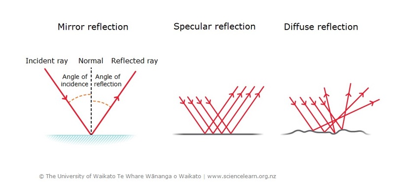
Reflection is when light bounces off an object. If the surface is smooth and shiny, like glass, water or polished metal, the light will reflect at the same angle as it hit the surface. This is called specular reflection.
Types of reflection
Light reflects from a smooth surface at the same angle as it hits the surface. For a smooth surface, reflected light rays travel in the same direction. This is called specular reflection. For a rough surface, reflected light rays scatter in all directions. This is called diffuse reflection.
Diffuse reflection is when light hits an object and reflects in lots of different directions. This happens when the surface is rough. Most of the things we see are because light from a source has reflected off it.
For example, if you look at a bird, light has reflected off that bird and travelled in nearly all directions. If some of that light enters your eyes, it hits the retina at the back of your eyes. An electrical signal is passed to your brain, and your brain interprets the signals as an image.
Specular reflection
The angle at which light hits a reflecting surface is called the angle of incidence, and the angle at which light bounces off a reflecting surface is called the angle of reflection

Lake reflection
This photo of Lake Matheson shows specular reflection in the water of the lake with reflected images of Aoraki/Mt Cook (left) and Mt Tasman (right). The very still lake water provides a perfectly smooth surface for this to occur.
If you want to measure these angles, imagine a perfectly straight line at a right angle to the reflective surface (this imaginary line is called ‘normal’). If you measure the angle of incidence and the angle of reflection against the normal, the angle of incidence is exactly the same as the angle of reflection. With a flat mirror, it is easy to show that the angle of reflection is the same as the angle of incidence.
Water is also a reflective surface. When the water in a lake or sea is very still, the reflection of the landscape is perfect, because the reflecting surface is very flat. However, if there are ripples or waves in the water, the reflection becomes distorted. This is because the reflecting surface is no longer flat and may have humps and troughs caused by the wind.
It is possible to make mirrors that behave like humps or troughs, and because of the different way they reflect light, they can be very useful.
Concave mirrors
The inside curve of a spoon is an example of a concave mirror
Concave mirror
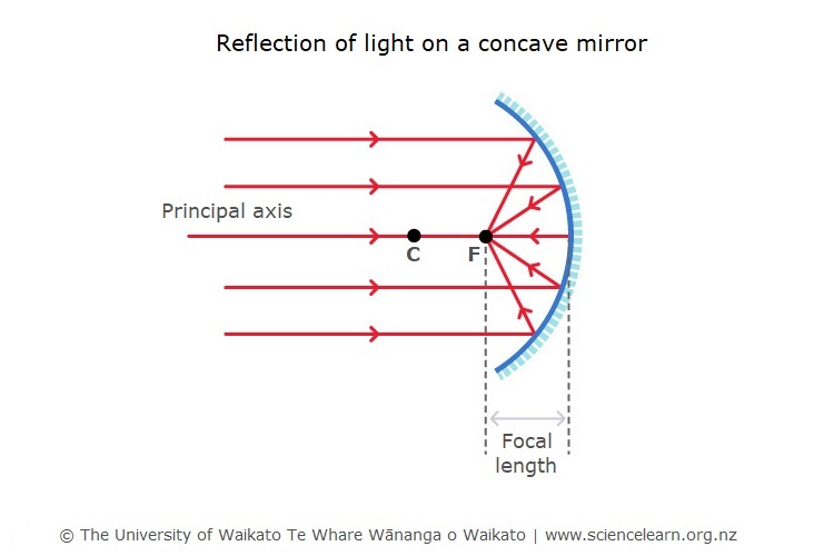
When parallel light rays hit a concave mirror they reflect inwards towards a focal point (F). Each individual ray is still reflecting at the same angle as it hits that small part of the surface.
Concave mirrors are used in certain types of astronomical telescopes called reflecting telescopes. The mirrors condense lots of light from faint sources in space onto a much smaller viewing area and allow the viewer to see far away objects and events in space that would be invisible to the naked eye.
Light rays travel towards the mirror in a straight line and are reflected inwards to meet at a point called the focal point.
Concave mirrors are useful for make-up mirrors because they can make things seem larger. This concave shape is also useful for car headlights and satellite dishes.
Convex mirrors
Convex mirrors curve outwards, like the outside of a balloon.

Convex mirror
When parallel light rays hit a convex mirror they reflect outwards and travel directly away from an imaginary focal point (F). Each individual ray is still reflecting at the same angle as it hits that small part of the surface.
Parallel rays of light strike the mirror and are reflected outwards. If imaginary lines are traced back, they appear to come from a focal point behind the mirror.
Convex mirrors are useful for shop security and rear-view mirrors on vehicles because they give a wider field of vision.
Scattering of light

Some light is scattered in all directions when it hits very small particles such as gas molecules or much larger particles such as dust or droplets of water.
The amount of scattering depends on how big the particle is compared to the wavelength of light that is hitting it. Smaller wavelengths are scattered more.
“Why is the sky blue?” is a common question. Light from the sun is made of all the colours of the rainbow. As this light hits the particles of nitrogen and oxygen in our atmosphere, it is scattered in all directions. Blue light has a smaller wavelength than red light, so it is scattered much more than red light. When we look at the sky, we see all the places that the blue light has been scattered from.
This is similar to the question: “Why are sunsets red?” When the Sun appears lower in the sky, the light that reaches us has already travelled through a lot more of the atmosphere. This means that a lot of the blue light has been scattered out well before the light arrives at us, so the sky appears redder.
Clouds appear white because the water droplets are much larger than the wavelengths of light. For this situation, all wavelengths of light are equally scattered in all directions.
Laws of Reflection
After understanding the meaning of reflection, you must also understand its two imperative laws. Using these laws, the reflection of the incident ray on various surfaces like a plane mirror, water, metal surfaces, etc can be determined. For instance, if we consider a plane mirror, here are the laws of reflection:
- The incident ray, the normal and the reflected ray must lie in the same plane.
- The angle of incidence (i) = The angle of reflection (r).

Types of Reflection
While exploring the basics of the reflection of light, it is also important to go through the different types of reflection. Whenever we change the basic elements or the form of basic elements involved in this phenomenon, the result also varies. Following are the main three types of reflection:
- Regular Reflection
- Diffused Reflection
- Multiple Reflection
Regular Reflection
Regular Reflection can also be referred to as Specular Reflection and is simply understood by using a plane mirror. This mirror used for reflection of light is not the regular mirror we see around us, rather it is a glass which is heavily coated with a uniform layer of highly reflective material such as a powder. As it is coated, the surface reflects all the light which falls on it i.e., there is not much variation in both the angles of reflection at multiple points. Due to this minimal variation, we can say that all the haziness and the blurriness are completely gone.

Diffused Reflection
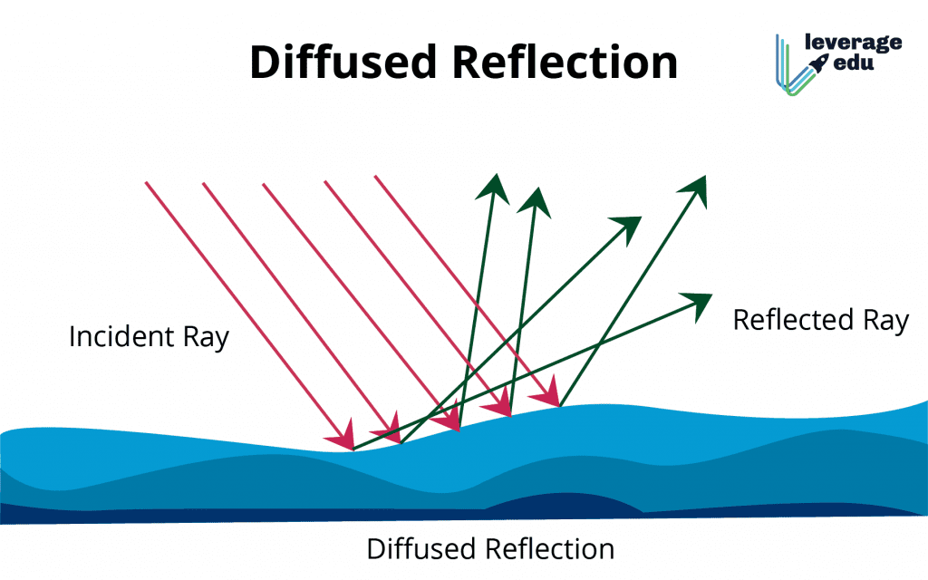
To explore the meaning of diffused reflection, let us consider reflective surfaces other than mirrors. The common surfaces which can be used for diffusion of light are comparatively rough as they are made up of different material than glass and contain some marks, scratches, dust or dents. All these things hamper the quality and brightness of reflection. Thus, the comparison of both the angles of reflection on such rough surfaces is completely distorted. In diffused reflection, the incident ray falls on different points and gets reflected in an entirely different direction and hence, we see non-shiny objects.
Multiple Reflection
For both regular and diffused reflection of light, a single mirror is used while when we take two mirrors, a single source of light can be reflected multiple times. This type of reflection is only possible when the intensity of the light becomes so low that we cannot see it. Infinite images will be formed in multiple reflections, as each image is the result of another image.
The number of images varies as per the angle between two mirrors. If we decrease the angle, the number of images increases. The number of images becomes infinite when the angle between the two mirrors is zero i.e, they are parallel. Here is a formula to calculate the number of images for diffused reflection of light:

Terminology used in reflection of light
- Incident ray : A light beam that strikes the mirror after emerging from an object or the source.
- Reflected rays : The light beam that bounces back after striking a reflective surface.
- Point of incident : It is the location where the incident ray makes contact with the surface.
- Normal : It is the line which is perpendicular to the reflecting surface at the point of incident.
- Angle of incidence : Angle of incidence is the angle formed at the point of incidence between the incident ray and the normal to the surface. It is represented by i.
- Angle of reflection : Angle of reflection is defined as the angle formed by the reflected ray and the normal to the surface at the point of incidence. It is represented by r.
- Angle of deviation : Angle of deviation is the angle formed by the directions of the incident and reflected rays. Angle of deviation is given by
Object and image
Object : An object is everything which is viewed. Also it is the point of intersection of the incident rays. The object can be real and virtual. When the incident rays actually meet (or emerge from) the object is called a real object (figure 1). When the incident rays appear to meet (or emerge from) then it is called a virtual object (figure 2).
Image : The point of intersection of reflected rays is called image. It can also be real and virtual. If the reflected rays appear to meet then it is called a virtual image (figure 1). If the reflected rays actually meet at a point then it is called real image (figure 2).


Practice problems
Q1. A light ray is incident on a plane surface at an angle 37o with the surface, what is the angle of reflection?
A. Given angle with the surface s = 37o
The angle of incidence i = 90o - s = 90o - 37o = 53o
As per the law of reflection, angle of incidence is equal to angle of reflection i = r
So the angle of reflection r = 53o.
Q2. The angle of incidence for a plane reflecting surface is  . What is the angle of deviation?
A. Given angle of incidence
The deviation's angle is given by,


The angle of deviation is  or 90o.
PRINCIPAL FOCUS:
The principal focus of a concave lens is a point on its principal axis from which light rays parallel to the principal axis, appear to diverge after refraction by the lens. It is usually represented by the letter ‘F’. However a concave lens has two spherical surfaces and hence it has two principal foci or two focal points which are usually denoted by the letters ‘F1’ and ‘F2’ and are known as the first principal focus ‘F1’ and the second principal focus ‘F2’. The two foci of a lens are at equal distances from the optical centre, one an either side of the lens.
Since the light rays do not actually pass through the focus (or foci) of a concave lens, therefore, a concave lens has a virtual focus.
(i) First Principal Focus (F1) : The first principal focus (F1) of a concave lens is the virtual position of a point object on the principal axis of the lens, for which the image formed by the concave lens is at infinity. It is usually denoted by the letter ‘F1’, as shown in the figure (a)
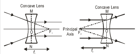
(ii) Second Principal Focus (F2): The second principal focus (F2) of a concave lens is the position of image point on the principal axis of the lens, when the object is situated at infinity. It is generally denoted by the letter (F2), as shown in the figure (b).
FOCAL LENGTH:
The distance of the principal focus (F1 or F2) from the optical centre ‘O’ of a lens is called its focal length. It is usually denoted by the letter ‘f ‘. Since a concave lens has two principal foci, so it has two focal lengths, known as : first focal length (f1) and second focal length (f2).
(i) First Focal Length (f1): The distance of first principal focus (F1) of the lens from optical centre ‘O’ of the lens is called first focal length of concave lens. It is represented by ‘F1’. i.e. OF1 = f 1. [see (a) in above figure].
(ii) Second Focal Length (F2): The distance of second principal focus (F2) of the lens from the optical centre ‘O’ of the lens is called second focal length of concave lens. It is represented by ‘f2’. i.e. OF2 = f2 [see (b) in above figure].
Rules for the formation of images by Convex Lens:
The positions of the image formed by a convex lens can be found by considering two of the following rays (as explained below).
(i) A ray of light coming parallel to principal axis, after refraction through the lens, passes through the principal focus (F) as shown in the figure.
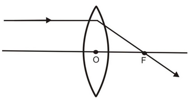
Convex Lens
(ii) A ray of light passing through the optical centre O of the lens goes straight without suffering any deviation as shown in the figure.
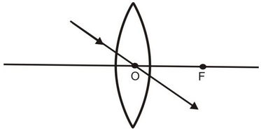
(iii) A ray of light coming from the object and passing through the principal focus of the lens after refraction through the lens, becomes parallel to the principal axis.
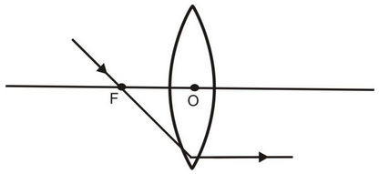
Image formed by Convex Lens:
The position, size and nature of the image formed by a convex lens depends upon the distance of the object from the optical centre of the lens. For a thin convex lens, the various case of image formation are explained below :
(i) When object at infinity:
When an object lies at infinity, the rays of light coming from the object may be regarded as a parallel beam of light. The ray of light BO passing through the optical centre O goes straight without any deviation. Another parallel ray AE coming from the object, after refraction, goes along EA’ Both the refracted rays meet at A’ in the focal plane of the lens. Hence, a real, inverted and highly diminished image is formed on the other side of the lens in its focal plane.
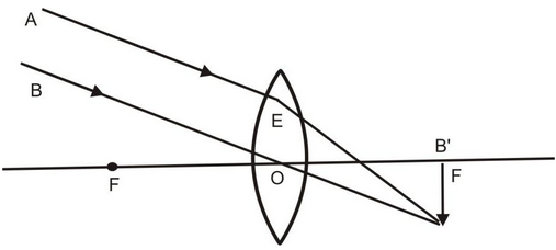
Real, Inverted and highly diminished image
(ii) When object lies beyond 2F:
When the object lies beyond 2F, its real, invert and diminished image is formed between F and 2F on the other side of the lens as explained below:
A ray of light AE coming parallel to the principal axis, after refraction, passes through the principal focus F and goes along EF. Another ray AO passing through the optical centre O goes straight without suffering any deviation. Both the refracted rays meet at A’. Hence, a real, inverted and diminished image is formed between F and 2F on the other side of the convex lens.
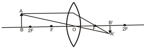
Real, inverted and diminished image
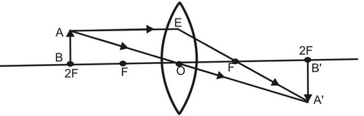
(iii) When object lies at 2F:
When an object lies at 2F, its real & inverted image having same size as that of the object is formed on the other side of the convex lens as explained below :
A ray of light AE coming parallel to the principal axis, after refraction, passes through the principal focus F and goes along EF. Another ray AO passing through the optical centre O goes straight without suffering any deviation. Both the refracted rays meet at A’. Hence a real, inverted image having the same size as the of the object is formed at 2F on the other side of the lens.
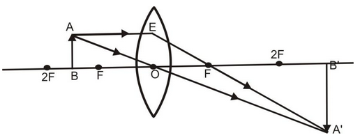
(iv) When object lies between F and 2F.
When an object lies between F and 2F in front of a convex lens, its real, inverted and magnified image is formed beyond 2F on the other side of the lens an explained below:
A ray of light AE coming parallel to the principal axis, after refraction, passes through the principal focus F and goes along EF. Another ray of light AO passing through the optical centre goes straight without any deviation. Both these refracted rays meet at A’. Hence a real, inverted and magnified image is formed beyond 2F on the other side of the lens.
(v) When object lies at F:
When an object lies at the principal focus F of a convex lens, then its real, inverted and highly magnified image is formed at infinity on the other side of the lens as explained below:
A ray of light AE coming parallel to the principal axis, after refraction, passes through the principal focus F and goes along EF. Another ray of light AO passing through the optical centre O goes straight without any deviation. Both these refracted rays are parallel to each other and meet at infinity. Hence, a real, inverted, highly magnified image is formed at infinity on the other side of the lens.
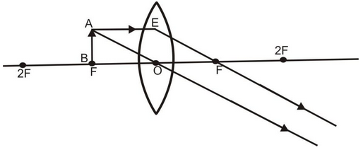
Meet at infinity
(vi) When object lies between O and F:
When an object lies between the optical centre O and the principal focus F of a convex lens, then its virtual, erect and magnified image is formed on the same side as that of the object as explained below :
A ray of light AE coming parallel to the principal axis, after refraction, passes through the principal focus F and goes along EF. Another ray of light AO passing through the optical centre goes straight without any deviation. Both these refracted rays appears to meet at A’. When produced backward. Hence a virtual, erect and enlarged image is obtained on the same side of the lens.
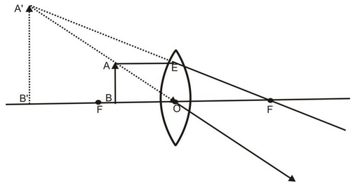
The results of image formation by a convex lens are summarised in the table:
Position of the object | Positon of the image | Size of the image | Nature of the image |
At infinity | At the focus F | Highly diminished | Real and inverted |
Beyond 2F | Between F and 2F | Diminished | Real and inverted |
At 2F | At 2F | Same size | Real and inverted |
Between F and 2F | Beyond 2F | Magnified | Real and inverted |
At F | At infinity | Highly magnified | Real and inverted |
Between O and F | On the side of the object | Magnified | Virtual and erect |
HOW TO FIND OUT THE APPROXIMATE FOCAL LENGTH OF A CONVEX LENS:
To find out the approximate focal length of a convex lens, focus a distant object (at infinity) on a screen by using a convex lens whose focal length is to be determined. The sharp and inverted image of this object will be formed at the focus of the convex lens. The distance of the image so formed from the convex lens is equal to the focal length of convex lens. Measure this distance with the help of a scale. It will give us the approximate focal length of the convex lens.
RULES FOR TRACING IMAGES FORMED BY CONCAVE LENS:
When an object is placed in front of a concave lens, its image is formed at a point where at least two refracted light rays appear to meet. To trace the position and nature of the image formed by a concave lens, the three rays of light are commonly used, out of which, we take any two rays of light (starting from the object) whose paths, after refraction from the lens are known to us and are easy to draw. We may call them (the three rays) as rules for tracing images in concave lens. These are as follows:
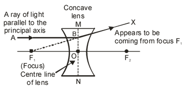
(i) A ray of light which is parallel to the principal axis of a concave lens, appears to be coming from its focus after refraction through the lens, as shown in the figure below.
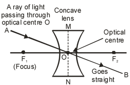
(ii) A ray of light passing through the optical centre ‘O’ of a concave lens goes straight (undeviated) after refraction through the lens, as shown in the figure. |
| |
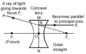
(iii) A ray of light appearing to pass towards the focus of a concave lens, becomes parallel to its principal axis after refraction through the lens, as shown in the figure. |
| |
FOR SPHERICAL LENSES:
- If linear magnification, m > 1, then the image is enlarged i.e., bigger than the object.
- If linear magnification, m = 1, then the image is of the same size as the object.
- If linear magnification, m < 1 the image is diminished i.e., the image is smaller than the object.
- If the magnification ‘m’ is +ve the image is virtual and erect. And if the magnification ‘m’ is –ve the image will be real and inverted.
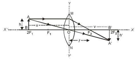
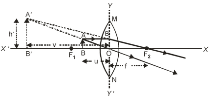
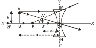
| (i) A concave Lens always forms an image smaller than the object. Therefore linear magnification (m) of a concave lens is less than one. (ii) A convex lens forms an image (i) equal in size to the object (i.e. m = 1) (ii) less than the size of the object (i.e. m<1) (iii) more than the size of the object (i.e. m > 1). Therefore linear magnification of a convex lens can be one, less than one or more than one. SOME IMPORTANT CONCLUSIONSOn the basis of the New Cartesian Sign Convention discussed above, we can draw the following conclusions for the spherical lenses (convex as well as concave lenses). IN CASE OF CONVEX LENS:(i) For real and inverted image Focal length (f ) = +ve Object distance (u) = –ve Object height (h) = +ve Image distance (v) = +ve Image height (h′) = –ve Magnification (m) = –ve
(ii) For virtual and erect image Focal length (f ) = +ve Object distance (u) = –ve Object height (h) = +ve Image distance (v) = –ve Image height (h′) = +ve Magnification (m) = +ve
In the case of a convex lens, for virtual and erect image, the object distance (u) and image distance (v) are –ve and remaining all distances are +ve. IN CASE OF CONCAVE LENS:Since a concave lens always forms virtual and erect image therefore For virtual and erect image Focal length (f ) = –ve Object distance (u) = –ve Object height (h) = +ve Image distance (v) = –ve Image height (h′) = +ve Magnification (m) = +ve
|

- Get link
- X
- Other Apps
Comments
Post a Comment